1 Splement Circuit Diagram
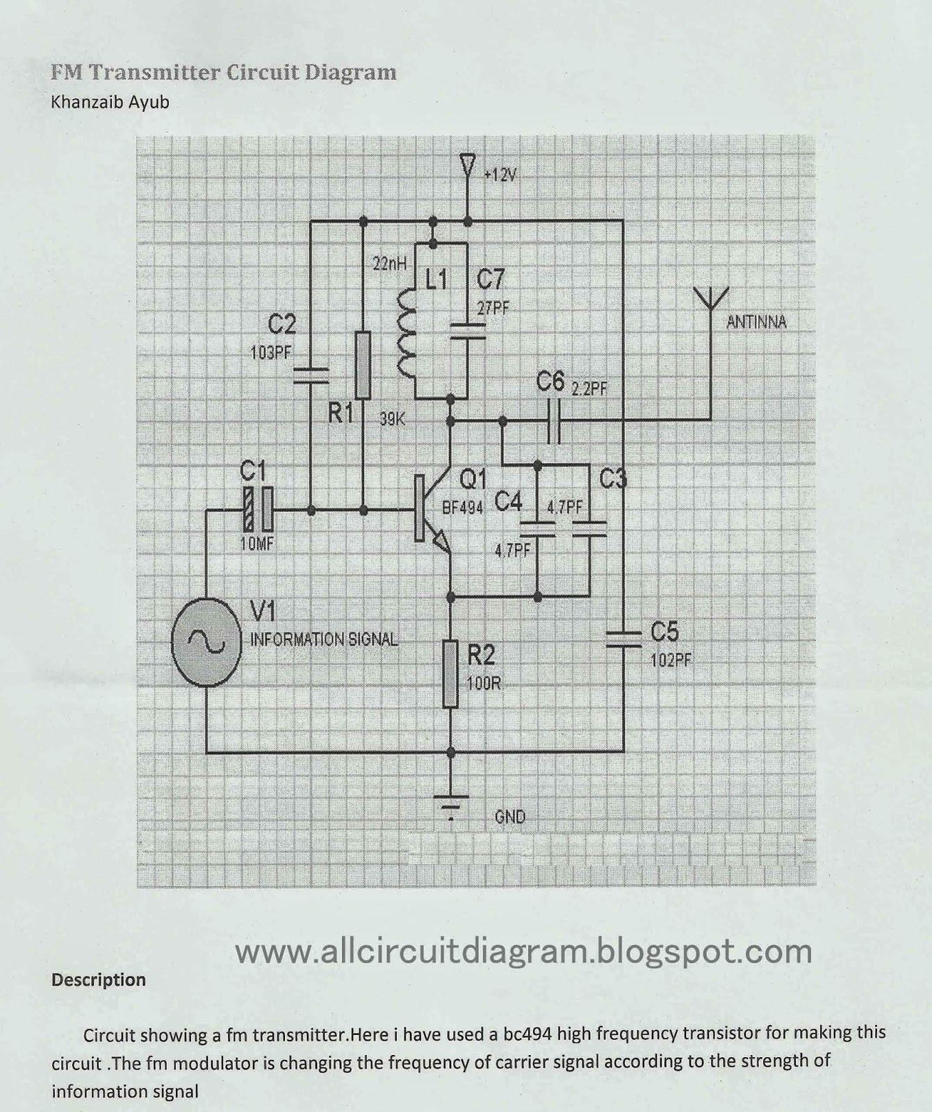
Ohm's law circuit diagram [how to read symbols] • ohm law Fm transmitter circuit diagram Circuit diagram: 1.5 watt fm transmitter circuit diagram
06. DRAW A CIRCUIT DIAGRAM with 3 cells in a battery, a fuse, 2 bulbs
1 to 15 minute timer circuit diagram, working and applications Circuit diagram law ohm symbols ohms instruments read understand components let Supply power variable 30v 5a circuit regulated eleccircuit output using benchtop lm723 dc regulator adjustable voltage current ca3140 source 24v
0-30v 0-5a regulated variable power supply circuit
Electricity battery bulb cells physics vacancesAdder cmos vlsi circuits circuit implement stack Circuits circuit physics conductors asvab electronic gcse studies bookingritzcarlton classics diagrams schematics magnetism restrictions under 출처 perov bitesize ks206. draw a circuit diagram with 3 cells in a battery, a fuse, 2 bulbs.
Circuit timer wiring resistor circuits electricaltechnology cctv componentTransmitter circuit fm watt range km diagram works .


Grade 6 - Circuits, Conductors and the Classics - International School Blog
.gif)
Circuit Diagram: 1.5 Watt FM Transmitter circuit diagram

FM Transmitter Circuit Diagram - Gallery Of Electronic Circuit Diagram Free

0-30V 0-5A regulated variable power supply circuit - ElecCircuit.com

Energy | Class 7 Science | Primary School - EsomaKe
![Ohm's law circuit diagram [How to Read Symbols] • Ohm Law](https://i2.wp.com/ohmlaw.com/wp-content/uploads/2018/02/ohm-law-circuit-diagram-with-instruments.png)
Ohm's law circuit diagram [How to Read Symbols] • Ohm Law

06. DRAW A CIRCUIT DIAGRAM with 3 cells in a battery, a fuse, 2 bulbs

vlsi - CMOS Adder circuits - Electrical Engineering Stack Exchange